
Below is a brief description of recent projects we have completed and is typical of what we do as well as servicing and breakdown calls
The lift in question was one of a 2 car group. They were both condemned 9 years ago by another lift company. The client only had the funds to repair one at the time so the lift we repaired had not run for 9 years. In the intervening years the client had been quoted very high prices to replace virtually everything. Parts had also been stripped to use on other old lifts owned by the client. We obtained the service contract on these flats and a sister block with another 2 lifts in 2017. Upon inspecting the shut down lift we were able to determine that a lot of it was capable of a bit more service. We supplied a quote to replace only what was necessary from a safety point of view or parts beyond economic repair. It was substantially below previous quotes which meant that it was acceptable to the client and we were given the order.
We replaced the obsolete express control panel, the drive gear and motor, new push station to DDA requirements in the lift car, New trailing flexes, new shaft positioning system and new main suspension ropes, as well as rewiring the installation. We were able to retain the existing lift car, guide rails, counterweight, all landing doors, car doors and door operating system and many auxiliary components.
Below are some photographs taken at various stages with a brief description.
Project 1 - Major refurbishment of 7 floor passenger lift in Colchester


The original Express DC motor and gear unit. Circa 50 years old.
Old gear being dismantled
Old gear removed. New gear awaiting extra steel crossmembers to be fitted to adapt it to fit


New gear & motor with new ropes fitted
Obsolete Express control panel to be replaced
New control panel mounted in position.
New controller is connected to the existing one to operate as a pair from one landing button. All shaft & car wiring is connected in new controller.
Project 2 - Complete Hydraulic System Replacement, Nursing Home, Clacton
We were contacted by the Nursing home owner after the lift had been switched off by his service company as it was in a dangerous condition. He was told that the lift needed total replacement. On arrival we were shocked to see the condition of the hydraulic oil tank housing the power unit, and the hydraulic piston driving the lift. It must have taken quite a while to get as corroded as it was. It was apparent that it had spent sometime submerged in water. See the photos below.
We could see that the main lift controller was not original and had been replaced at some time previously and was still serviceable. The car doors and door drive was only a few years old and although not working it could be repaired and retained. We suggested to the client that we could replace only the corroded hydraulic tank/pump unit, hydraulic hoses and piston. The cost was a fraction of the price for a new lift and would work just as well.
The new tank/pump unit was housed in a large plastic water tank so that in the event of flooding it would be protected. The new piston was raised slightly from the ground and mounted on a waterproof plinth that we had made to keep it clear of water in the lift pit.


The corrosion was so bad that the welds at the bottom of the tank were starting to leak oil. The bottom of the piston was so badly rusted that the steel had thinned considerably. This was dangerous as the piston operates under high pressure. Water had got into the tank and mixed with the oil and started emulsifying.


The new tank and pump unit after completion. It was mounted inside a large cold water storage tank to protect it from future flooding. The new hydraulic hose can be seen which goes through the wall into the lift shaft and connects to the new piston. it was filled with fresh oil.
The broken busmatic type folding doors were overhauled and fitted with new bearings and adjusted properly.

Project 3 - A Technical Challenge
We were contacted by a customer wanting us to quote for a service contract on 2 lifts. He explained that although they were supposed to operate together, they were alternating by using one for a month and then switching it off and using the other for a month. He went on to say that the reason for this was because they had a lightning strike about 4 years previous which had destroyed on of the lifts main controller. The service company they were using at the time had replaced the controller with one that was incompatible with the other, (we don't know why as a compatible controller was available at the time). This meant that they could not operate properly together as both lifts answered every landing call. They were told that nothing could be done without replacing the other controller which was very expensive. So it was decided to use only one lift at a time.
Our managing director, who has over 35 years experience and vast technical knowledge. was intrigued and went to see for himself. It was indeed a case of the controllers could not work together. However our MD came up with a plan to design and build an interface panel to link both controllers. All the landing calls would be routed to the new panel and then despatched to the main controllers alternately. This would allow both lifts to be used together with only one lift at a time answering landing calls alternately. The customer was extremely pleased that after 4 years something could be done at reasonable cost.
There were several challenges in the design of the interface board. One of which was what would happen if the lift designated to answer the call was being held by the postman or whoever, or what would happen if one lift had to be switched off. We put timers into the circuit to automatically switch the call to the other lift if the designated one did not respond within a set time. The circuitry was also designed to automatically route all calls to the other lift if one was switched off.
The interface was designed and built by us in house. We know of no other lift company that could/would have done this.

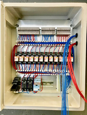
Interface board under construction.
The picture on the left shows the backing panel with all the relay bases and components fitted.
The picture on the right shows the completed panel after wiring. The relays are plugged into the bases.

The picture on the left shows the panel fitted in its cabinet on site. The blue wires are the interconnections from one main controller and the reds from the other.

In the photo above, our interface panel can be seen on the wall to the left, beneath one of the main controllers. There is some complicated interconnecting wiring going on here. The other main controller is to the right of this one and can't be seen in the picture. At the time of writing it has been working trouble free for nearly 2 years.
Project 4 - Obsolete Lift Refurbishment & Repair, Woodbridge.
Our customer contacted us to ask for a quote for a new lift. They had been told by their lift service company that the lift was not repairable after a breakdown, and that the whole lift would need replacement as it was obsolete. Upon reading the previous engineers report it was stated that there was a fault on the controller and the drive motor was faulty.
We informed the customer that we could upgrade the existing lift including repairing the motor windings, reconditioning the motor/gearbox with new bearings, new shaft positioning system for better floor level accuracy, new drive chains, and more importantly we could design and build a new main controller in house to replace the obsolete one. All this came in at less than a third of the price quoted for a new lift and would be just as reliable. Our proposal was accepted and at the time of writing it has been completed for 8 months without a single problem.
Please see pictures below.


Faulty obsolete controller & motor with faulty windings restricted space at the top of the shaft. The motor/gear unit was removed for repair and overhaul. The controller was removed and replaced with a custom made unit.

New motor/gearbox assembly ready to be fitted on site
.jpg)
New motor/gear fitted. New chains also fitted

New shaft positioning system being fitted.

Repaired motor refitted to overhauled gearbox ready for testing. New controller nearing completion.

New controller fitted at top of shaft.